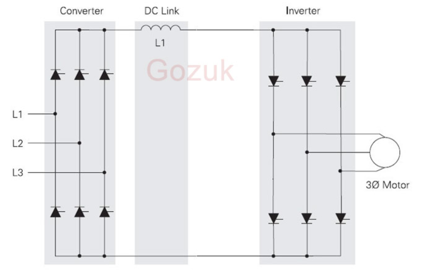
Inverter phase voltage source three circuit vsi power diagram 12+ 3 phase inverter circuit diagram Power circuit of a three-phase voltage source inverter (vsi
Voltage Source Inverters (VSI) Operation | VSI Working Principle
Inverter circuit transistor 220v 3v Simplest power inverter circuit using a single 555 ic Voltage source vsi inverter circuit inverters principle operation working power dc
What is current source inverter? definition, control & closed loop
Inverter voltage circuit source diagram motor figure variable frequencyInverter voltage circuit ii schematic simple power diagram supply electronic circuits parts dc converter produce negative inexpensive positive dual single 15 transistor inverter circuit diagramInverter 555 circuit ic circuits using power wave diagram bridge output single simplest square type will homemade explored simple parts.
Inverter circuit voltage diagram schematic using circuits ne555 ups generator power ic internal adjustable generate possible shows many need useVoltage source inverters (vsi) operation Current inverter source motor induction drive fed control circuit controlled operation dc link closedHigh voltage inverter circuit diagram.

Voltage inverter circuit
Inverter conduction inverters switching sine schematics circuitdigestSingle phase half bridge inverter explained Inverter as high voltage low current source circuit diagramElectrical video library: v/f control of induction motor.
Inverter voltage schematicA circuit diagram of a three-phase voltage source Inverter phase diagram principleInverter voltage high current low source circuit diagram 555 timer power schematics circuits ic using electronic.

Electrical video library: v/f control of induction motor
1, three phase inverter circuitPhase voltage three circuit source diagram inverter step six question answered hasn yet been operates Voltage inverter using a 555 schematic circuit diagramInverter current circuit source diagram figure.
How to make a simple inverter circuit at homeInverter circuit diagram simple diy electrical projects wiring electronic electronics make using power ac engineering 12v dc newcomers easy circuits Voltage inverter high circuit diagram 3v schematic electronic diy elcircuit dc transistor electrical.


What is Current Source Inverter? Definition, Control & Closed Loop

1, Three phase inverter circuit | Download Scientific Diagram
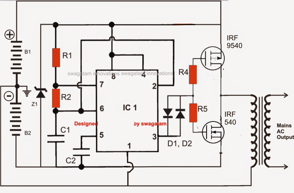
Simplest Power Inverter Circuit Using a Single 555 IC | Circuit Diagram

Voltage Inverter using a 555 Schematic Circuit Diagram

Single Phase Half Bridge Inverter Explained - Electrical Concepts

15 Transistor Inverter Circuit Diagram | Robhosking Diagram
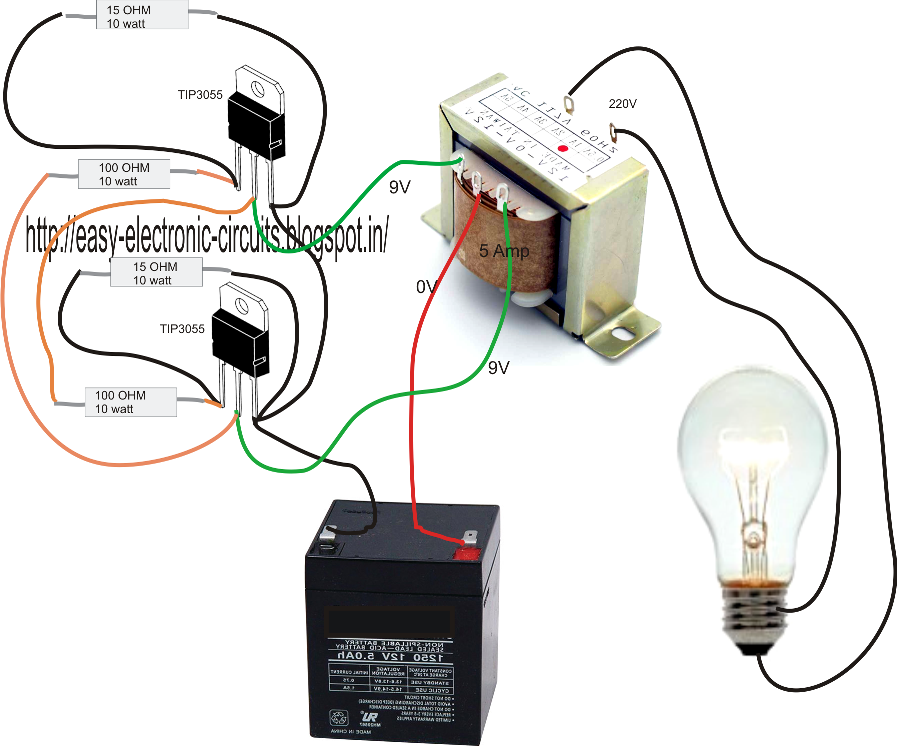
How to Make a Simple Inverter Circuit at Home - ElectricalCoreCircuits

ELECTRICAL VIDEO LIBRARY: v/f control of induction motor
ELECTRICAL VIDEO LIBRARY: v/f control of induction motor